Research Article > DOI
Dean Čizmar 
2026 | Volume 1 | e006
Received: 10 May 2026 | Revised: 6 June 2026 | Accepted: 24 June 2026 | Published: 11 July 2026
Abstract
Numerical models of timber trusses used in engineering practice and structural condition assessment typically assume pin-jointed web-to-chord connections. This article demonstrates that such models systematically underestimate measured vertical displacements — by 3 to 44% at the first load point (U₁) and 48 to 70% at midspan (U₂) — which is unsafe from a serviceability assessment perspective. An alternative spring model is proposed in which longitudinal and rotational slip moduli of the connections are incorporated explicitly. Results are presented for six full-scale timber trusses with two fastener types (Wolf 15N punched metal plate fasteners, PMPF, and M10 bolts) and two timber grades (C24 solid timber and GL24h glulam). The spring model reduces the U₁ error to within ±15% for five of six configurations and achieves 3–6% accuracy for midspan displacement U₂ in bolt-fastened trusses. One exception is identified: for the N-web truss with Wolf 15N plates (R1), the spring model overestimates U₁ by 26.5%, attributed to overrepresentation of the rotational spring contribution for that geometry. Experimentally determined longitudinal slip moduli agree well with normative values. Rotational stiffness of Wolf 15N plates is reported experimentally for the first time. Implications for robustness assessment of existing timber roof structures are discussed.
Keywords
timber truss, pin-joint model, spring model, connection slip modulus, serviceability assessment, punched metal plate fastener
How to Cite: Cizmar D. Numerical modelling of timber trusses for serviceability assessment: accuracy of pinjoint and spring models. Resilience and Reuse in the Built Environment. 2026; 1:e006.
Download .RIS Download .BibTeX
Link: doi
Introduction
Timber trusses remain a predominant structural form for roof systems in residential and commercial construction across Central and Southeastern Europe. In Croatia alone, the estimated stock of buildings with light timber roof trusses erected between 1960 and 2000 exceeds 400,000 units [1], a substantial proportion of which were designed before the introduction of Eurocode 5 (EN 1995-1-1) [2] and are subject to periodic condition assessment under current regulations. Accurate numerical modelling of these structures is a prerequisite for reliable serviceability verification and robustness assessment — both critical for decisions on continued service, strengthening, or adaptive reuse.
The standard modelling assumption in practice and in most assessment software is the pin-jointed truss: web-to-chord connections are idealised as moment-free hinges that transmit only axial forces, and joint deformability (connection slip) is ignored. This idealisation is conservative for strength verification of connections but non-conservative for displacement prediction. Research conducted over the past four decades consistently reports that pin-joint models underestimate measured deflections of timber trusses by 20–70% [3,4,5], a discrepancy that has direct consequences for serviceability limit state checks and for force redistribution analyses in damaged systems.
Connection slip arises from two physically distinct mechanisms. Longitudinal slip (translation of one connected member relative to the other along the member axis) reduces the effective stiffness of web elements and is captured by the slip modulus Kₛₑᵣ defined in EN 1995-1-1 [2]. Rotational slip (relative rotation of the web element with respect to the chord at the connection) increases chord rotation and midspan deflection; it is not explicitly addressed in EN 1995-1-1 for punched metal plate fasteners and has rarely been measured experimentally [1]. The combined effect of these two mechanisms depends on web topology: for V- and K-web trusses where diagonals are inclined at large angles, rotational slip dominates and pin-joint errors are largest; for N-web trusses with smaller inclination angles, longitudinal slip is more significant.
This article makes the following specific contributions: (1) quantification of pin-joint model displacement error across six timber truss configurations covering four web topologies, two timber grades, and two fastener types; (2) experimental determination of longitudinal and rotational slip moduli for Wolf 15N punched metal plate fasteners and M10 bolts, including the first reported experimental values of Wolf 15N rotational stiffness; (3) validation of a spring model against full-scale truss tests; (4) identification and physical explanation of one exception to the general improvement achieved by the spring model; and (5) discussion of implications for robustness assessment of existing timber roof structures. These six truss configurations are illustrated in Figure 2.
Methods
Truss configurations and experimental programme
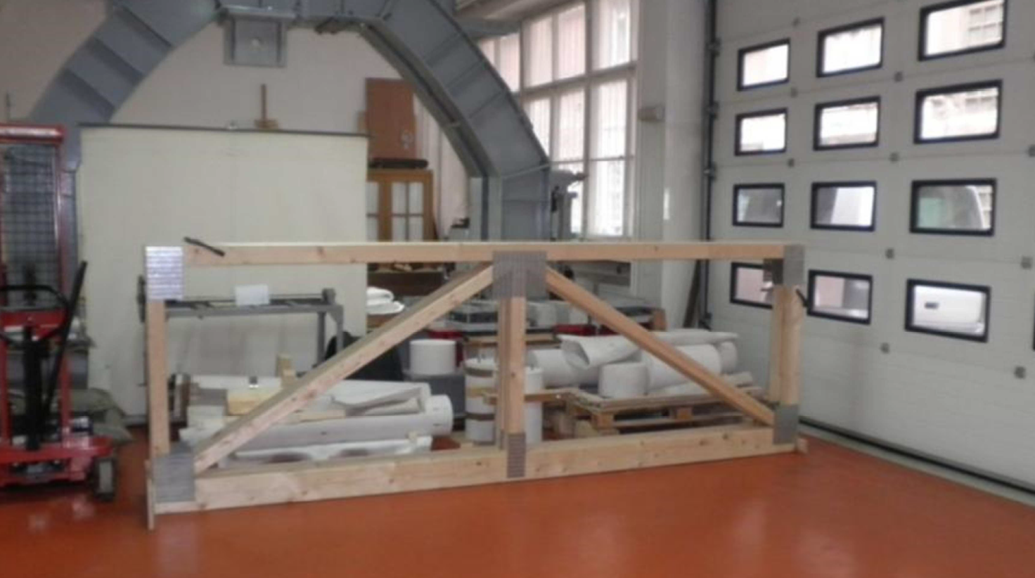
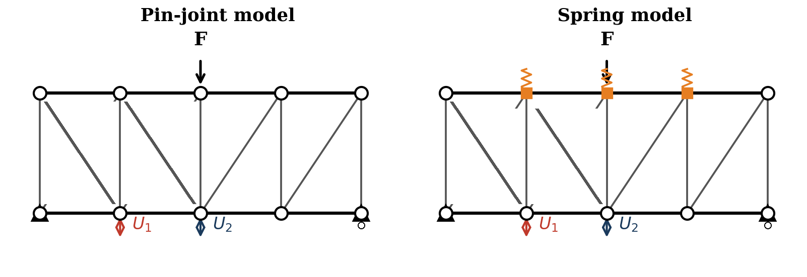
Six timber truss configurations were fabricated and tested at the Laboratory for Structural Testing, Faculty of Civil Engineering, University of Zagreb. Table 1 summarises the configurations. All trusses that were tested experimentally had a span of 368 cm and were subjected to a concentrated force applied at midspan by a displacement-controlled hydraulic actuator. Displacement was measured at three positions: U₁ (first-quarter span on the upper chord), U₂ (midspan), and U₃ (third-quarter span); positions U₁ and U₂ are indicated schematically in Figure 3. Loading was applied at a rate of 0.2 mm/min up to approximately 60% of the estimated failure load, then unloaded. Results reported herein correspond to 40% of the maximum force in the first loading cycle, ensuring linear elastic response. A representative truss specimen prepared for testing is shown in Figure 1.
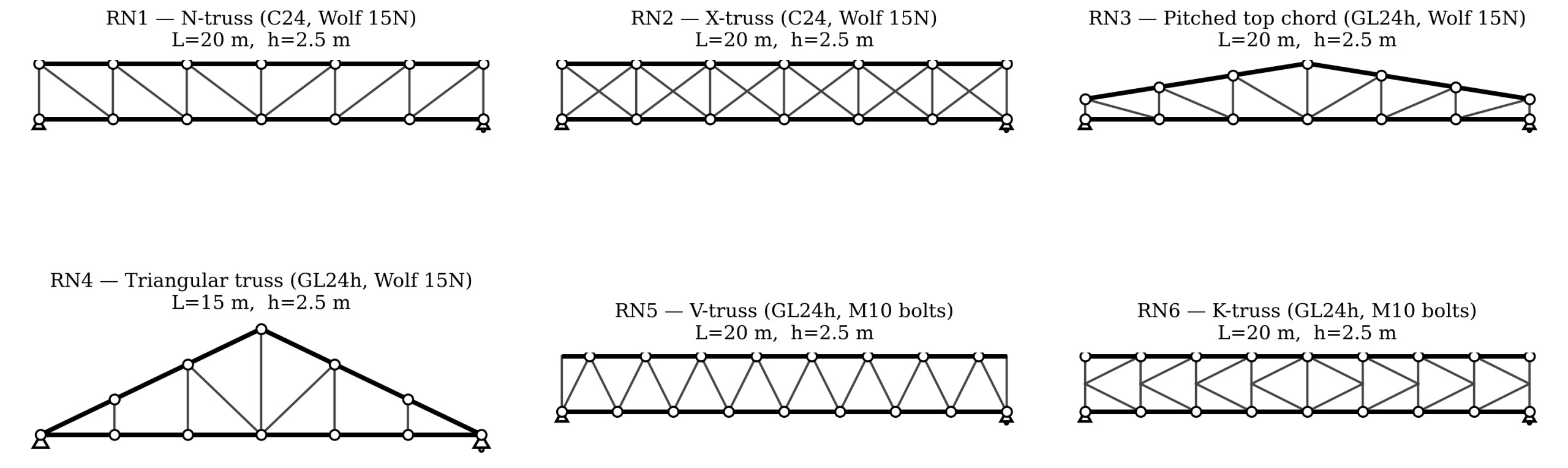
Throughout this article, designations R1–R6 refer to the six physical truss specimens tested experimentally, while designations RN1–RN6 are used in companion publications [6,7,14] to denote the corresponding probabilistic models for robustness assessment. The two designation systems refer to the same six structural configurations but reflect their distinct analytical purposes (experimental vs. probabilistic).
Table 1. Timber truss configurations tested.

Slip modulus determination
Slip moduli were determined from dedicated small-specimen tests conducted independently of the truss tests, following EN 1075 [8] for punched metal plate fasteners and EN 12512 [9] for bolted connections. The secant modulus between 10% and 40% of maximum force (Kₛₑᵣ,ₛₑc) was used as the representative value, consistent with EN 1995-1-1 serviceability provisions. The rotational stiffness of Wolf 15N plates was determined from dedicated rotation tests in which the plate connection was subjected to pure moment, while the rotation between connected members was measured by two linear transducers. Three specimens were tested for each configuration. The rotational stiffness of Wolf 15N is reported experimentally here for the first time.
The normative slip modulus for bolted connections is given in EN 1995-1-1 [2], Table 7.1, per shear plane per fastener, as:

where ρm is the mean timber density (kg/m³), and d is the bolt diameter (mm). The normative value reported in Table 2 was computed with the mean density measured on the test batch in the original experimental study [1]. For Wolf 15N plates, the declared longitudinal slip modulus from the German approval document (DIBt Z-9.1-535) [10] is 2.33 N/mm³ per unit plate area; no rotational stiffness is declared.
Numerical models
Two numerical models were implemented in the planar frame analysis software for each truss configuration. The pin-joint model releases rotational degrees of freedom at all web-to-chord connections, resulting in a statically determinate truss for N- and V-web configurations. The spring model replaces the moment releases with elastic rotational springs of stiffness Kₛₑᵣ,ᵣₒₜ and longitudinal springs of stiffness Kₛₑᵣ,ₗₒₙᴳ at each connection. Spring stiffnesses were computed from experimentally determined unit moduli (Table 2) multiplied by the effective contact area or number of fasteners as appropriate, following the procedure described in [5]. For the PMPF connections, the axial and rotational spring stiffnesses of each connection were obtained as:

where kser,long (N/mm³) and kser,rot (N/(rad·mm)) are the unit slip moduli per plate contact area given in Table 2, and Aef (mm²) is the effective plate contact area on the connected member. For the bolted connections with n fasteners per connection, the corresponding stiffnesses were obtained as:

where Kser is the slip modulus per fastener per shear plane according to Equation (1) or Table 2, and ri is the distance of fastener i from the centroid of the fastener group. The general framework for incorporating semi-rigid joint behaviour in timber truss analysis applied here follows Larsen [11]. Model validation against Staad Pro V8i for elastic response showed relative differences below 0.5% in all member forces [5].
Results
Experimental slip moduli
The experimentally determined slip moduli for the two fastener types are summarised in Table 2. For Wolf 15N punched metal plate fasteners, the experimental longitudinal slip modulus (2.59 N/mm³) exceeds the declared value (DIBt 2009 [10]) by 11%. Rotational stiffness values for Wolf 15N (5.02 and 5.53 N/(rad·mm) for parallel and perpendicular orientations) are reported here on an experimental basis.
Table 2. Experimentally determined slip moduli for Wolf 15N punched metal plate fasteners and M10 bolts (class 8.8), compared with normative and declared values.

Displacement comparison — all configurations
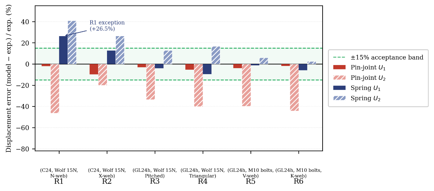
The ±15% acceptance range adopted here as an engineering tolerance for serviceability assessment reflects the cumulative typical uncertainty from four sources: (i) experimentally determined slip moduli (COV ≈ 3–5%), (ii) displacement measurement repeatability (≈ 3–5%), (iii) timber material variability within a single batch (≈ 5–8%), and (iv) modelling idealisations (e.g., perfect geometric symmetry, no eccentricity at joints). Propagated to a serviceability prediction, the cumulative uncertainty justifies a tolerance band of ±15%. This is also consistent with engineering tolerances reported in the timber truss modelling literature [3,4], where prediction errors of 5–15% are commonly considered acceptable agreement.
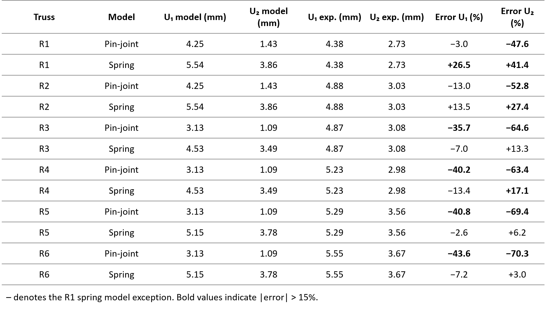
Table 3 presents the computed and measured displacements U₁ and U₂ for both models and all six truss configurations. Figure 4 shows the displacement errors graphically, with a shaded band indicating the ±15% acceptance range adopted here as an engineering tolerance for serviceability assessment. As evident from Figure 4, the pin-joint model consistently underestimates the measured displacements, while the spring model achieves acceptable accuracy for U₁ in five of six configurations; the single exception (R1, +26.5%) is examined in the Discussion.
Table 3. Computed (model) and measured (exp.) displacements and prediction errors for pin-joint and spring models.
Slip modulus validation
The experimentally determined longitudinal slip modulus for Wolf 15N plates (2.59 N/mm³, COV = 0.04) exceeds the declared value of 2.33 N/mm³ by 11%, indicating that the conservative declared value is suitable for design but may slightly underestimate actual joint stiffness. Load-displacement characteristics of punched metal plate connections under combined loading, as reported by Gupta and Gebremedhin [12], confirm that metal-plate joint behaviour under in-plane truss forces is predominantly governed by the slip modulus in the serviceability range. For M10 bolts, the experimental mean (3.08 kN/mm) agrees with the Eurocode 5 predicted value of 2.96 kN/mm (ratio 1.04), confirming the adequacy of the normative formula for this fastener type.
The rotational stiffness of Wolf 15N plates, reported experimentally for the first time in this article, is 5.02 N/(rad·mm) parallel to the grain direction and 5.53 N/(rad·mm) perpendicular to the grain direction. These values are used in the spring model for all Wolf 15N-fastened configurations.
Discussion
Physical mechanism of pin-joint error
The systematic underestimation of displacements by the pin-joint model arises from two additive sources: longitudinal slip and rotational slip. For the N-web truss (R1), diagonals are inclined at relatively small angles to the chord, so the moment arm of the connection is small and rotational slip contributes less. Longitudinal slip remains significant but is partially offset by the fact that N-web geometry generates lower force levels in individual web members compared to V- or K-web configurations. The X-web truss (R2) shows a similarly low pin-joint error (−13.0% for U₁), consistent with its double-diagonal configuration distributing panel shear between two members rather than one. This explains why the pin-joint error for R1 (C24, N-web) is the smallest in the set (−3.0% for U₁), while R6 (GL24h, K-web) has the largest error (−43.6%).
For GL24h trusses with bolt connections (R5, R6), rotational slip dominates because M10 bolts have substantially higher rotational flexibility than Wolf 15N plates (implied by the higher U₂ errors). The V- and K-web geometries amplify rotational effects because the larger inclination angle of diagonals generates larger bending moments at connections under midspan loading. This is consistent with the findings of Vatovec et al. [4] for similar web geometries.
The R1 spring model exception
There have been several research projects focused on the use of UAVs for heritage. Table 1 shows a selection of projects and initiatives related to heritage documentation in Europe. In the following, we summarise some of the challenges encountered within the mentioned projects regarding the application of UAVs for heritage documentation, as identified in the reviewed studies.
The only case where the spring model performs worse than the pin-joint model for U₁ is truss R1 (C24, Wolf 15N, N-web), where the spring model overestimates U₁ by 26.5%. The physical explanation is that for N-web geometry with horizontal parallel chords, the rotational spring at web-to-chord connections contributes relatively little to the actual joint rotation under the applied load pattern, because the diagonal forces pass close to the theoretical pin-joint location. The rotational spring stiffness Kₛₑᵣ,ᵣₒₜ = 5.02 N/(rad·mm), determined from pure rotation tests, may overstate the rotational contribution in the coupled loading condition of the truss. A sensitivity analysis shows that the R1 spring model error falls within ±15% when the rotational flexibility attributed to the connections (i.e., the rotational slip contribution to the global displacement) is reduced by 40%, which corresponds to a proportional increase of the rotational spring stiffness Kₛₑᵣ,ᵣₒₜ in the numerical model.
The practical implication is important for assessment practice: for N-web trusses with punched metal plate fasteners (a common roof configuration in Croatian residential construction built before 1990), the pin-joint model is adequate for U₁ verification but not for U₂. The spring model with experimentally or normatively determined parameters should be used when midspan deflection controls the serviceability check.
Implications for the assessment of existing timber structures
The results have direct relevance for structural condition assessment and serviceability verification of existing timber roof trusses, which constitute a large proportion of the built environment in Croatia and similar regions. When an existing structure is assessed for compliance with current serviceability limits (typically L/300 for characteristic load combination, L/200 for quasi-permanent under EN 1995-1-1 cl. 7.2), the choice of numerical model can determine whether the structure passes or fails. A pin-joint model underestimating deflections by 40–70% could lead to acceptance of a structure that, in reality, violates serviceability limits under current loading.
Furthermore, for robustness assessment under the framework developed by Rajčić et al. [7] and formalised axiomatically in [14], the internal force distribution in the damaged system depends directly on the global stiffness model. The transition from pin-joint to spring model changes component reliability indices by 5–18% depending on element type, as documented in a companion study [6]. This change is not uniformly conservative: spring models may yield lower reliability indices for compression-governed elements while increasing indices for tension elements. For this reason, the pin-joint model cannot be considered a generally conservative choice for robustness assessment of existing timber roofs. The potential for plastic redistribution through ductile connection behaviour further motivates the use of accurate stiffness models in robustness assessment [13].
For bolt-fastened trusses (R5, R6), the spring model achieves excellent accuracy (U₂ error 3–6%) using normative Kₛₑᵣ from EN 1995-1-1 equation (1) without any experimental input. This means that a reliable assessment of this common truss type is achievable from documentary evidence alone — a practically important result given that experimental testing of existing structures is frequently constrained by access, cost, or the need to preserve the structure during assessment.
Sensitivity to Kₛₑᵣ variability
The COV of slip modulus for bolted connections (COV = 0.40) is high, reflecting joint-to-joint variability in timber density and fastener placement. A sensitivity analysis shows that varying Kₛₑᵣ within ±1σ (range 1.90–4.18 kN/mm for M10 bolts) changes the spring model U₁ prediction for R5 by approximately ±18%. For serviceability assessment, it is therefore recommended to use the lower characteristic value of Kₛₑᵣ (i.e., mean minus one standard deviation) rather than the mean, to avoid non-conservative displacement predictions. This recommendation is consistent with the general principle that serviceability design should avoid underestimating deformations.
Limitations and future work
The findings of this study have several limitations that should be considered when applying the conclusions in practice. (i) Results are based on six truss configurations representative of typical European practice; broader validation against more configurations, span ranges, and timber grades is recommended. (ii) Loading is monotonic and quasi-static; cyclic behaviour and long-term creep effects of connection slip are not addressed. (iii) The moisture content of timber was controlled at the time of testing (12 ± 1%); in-service moisture variations may modify the slip moduli, particularly the rotational component, and warrant further investigation. (iv) Rotational stiffness values for Wolf 15N reported herein are based on three specimens per orientation; broader experimental campaigns would refine the statistical characterisation (mean and COV) of these parameters. (v) The R1 spring model overestimation (+26.5% for U₁) suggests that for certain truss topologies — specifically N-web configurations with low diagonal inclination — a refined geometric representation of the plate moment contribution may be required; this is identified as a topic for future work.
Conclusion
The following conclusions are drawn from the experimental and numerical comparison of pin-joint and spring models for six timber truss configurations:
(1) The pin-joint model systematically underestimates measured vertical displacements for all six configurations tested, with errors ranging from −3% to −44% for U₁ and −48% to −70% for U₂. This underestimation is non-conservative for serviceability verification and for robustness assessment of existing timber roof structures.
(2) The spring model, with slip moduli taken from experimental testing or from normative/declared values, reduces U₁ errors to within ±15% for five of six configurations and achieves 3–6% accuracy for U₂ in bolt-fastened trusses. The improvement is most significant for GL24h trusses with M10 bolt connections (V- and K-web).
(3) One exception is identified: truss R1 (C24, Wolf 15N, N-web) where the spring model overestimates U₁ by 26.5%. This is attributed to the overrepresentation of rotational spring stiffness for N-web geometry. For this configuration, the pin-joint model is adequate for U₁ but not for U₂; the spring model remains more accurate for U₂ verification.
(4) Experimentally determined longitudinal slip moduli agree with normative and declared values within 11% (Wolf 15N) and 4% (M10 bolts). Rotational stiffness of Wolf 15N punched metal plate fasteners is reported experimentally for the first time: 5.02 N/(rad·mm) parallel and 5.53 N/(rad·mm) perpendicular to the grain direction. These values are not available from manufacturer declarations.
(5) For the assessment of existing timber roof trusses, the spring model with normative parameters can be applied without experimental testing for bolt-fastened configurations, providing reliable serviceability predictions from documentary evidence alone. For punched metal plate fastener configurations, rotational stiffness from experimental testing or from values reported here should be used.
Author Contributions
Dean Čizmar: Conceptualisation, Data Curation, Formal Analysis, Investigation, Methodology, Visualisation, Writing – original draft, Writing – review & editing. The author has read and agreed to the published version of the manuscript.
Conflicts of Interest
The author declares no conflict of interest.
Funding
This research received no external funding.
Data Availability Statement
The data presented in this study are available on request from the corresponding author.
References